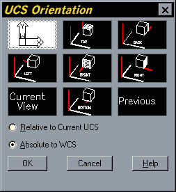
The two UCS icons above each represent WCS. The difference is explained below. Above is the stock 2D UCSICON shown in WCS. We know it is WCS because of either the 'W' or the square at the intersection of the X and Y axis. There are two different icons for WCS because you can choose to have the UCSICON visible as 2D or 3D. Moving and rotating the UCS is convenient when working in 2D, and essential when working in 3D. You can change the location and orientation of the current UCS by clicking the UCS icon and using its grips, or you can use the options in the UCS command. For example, clicking on the UCS icon displays its grips. Then, click on the square origin grip (1) and click the endpoint of its new location. Type 1 to use UCS values, or; Type 0 to use WCS values; Note: The USERR3 command only toggles between your UCS and the WCS as they relate to specific items such as Northing/Easting Points. If you need your entire drawing to reference one or the other, please follow our instructions to restore a UCS or restore the WCS. As an integer code that specifies the WCS, current UCS, or current DCS (of either the current viewport or paper space). As an entity name returned by one of the entity name or selection set functions. This specifies the OCS of the named object. If the OCS does not differ, conversion between OCS and WCS is an identity operation.
The TranslateCoordinates method translates a point or a displacement from one coordinate system to another.
A point argument, called OriginalPoint, can be interpreted as either a 3D point or a 3D displacement vector. Rimworld soundtrack crack. This argument is distinguished by the Boolean argument, Disp. If the Disp argument is set to TRUE, the OriginalPoint argument is treated as a displacement vector; otherwise, it is treated as a point. Two more arguments determine which coordinate system the OriginalPoint is from, and to which coordinate system the OriginalPoint is to be converted. The following AutoCAD coordinate systems can be specified in the From and To arguments:

Differentiate Between Ucs And Wcs In Autocad 2013
Polyline and LightweightPolyline objects are expressed in this coordinate system, relative to the object. These points are usually converted into the WCS, current UCS, or current DCS, according to the intended use of the object. Conversely, points in WCS, UCS, or DCS must be translated into an OCS before they are written to the database by means of the same properties.
Ind 560 manual. When converting coordinates to or from the OCS you must enter the normal for the OCS in the final argument of the TranslateCoordinates function.
Translate OCS coordinates to WCS coordinates
This example creates a polyline in model space. The first vertex for the polyline is then displayed in both the OCS and WCS coordinates. The conversion from OCS to WCS requires the normal for the OCS be placed in the last argument of the TranslateCoordinates method.
Depending on what discipline you work in, you may or may not have the need to work with User Defined Coordinate Systems. By default, a new empty AutoCAD drawing starts out in the World Coordinate System (WCS) by which all objects are defined. You are free to define any other User Coordinate System (UCS) at any time.
If you have ever tried to copy an item from one drawing to another and the copy does not come in where you think it should, you might be dealing with a different UCS in each drawing. That is why it is important to leave the UCSICON visible so that you can easily tell at least some initial indicators about the UCS.
The two UCS icons above each represent WCS. The difference is explained below.
Above is the stock 2D UCSICON shown in WCS. We know it is WCS because of either the 'W' or the square at the intersection of the X and Y axis. There are two different icons for WCS because you can choose to have the UCSICON visible as 2D or 3D. The dialog below can be found by running the UCSICON command and then 'P' for properties.
The UCSICON has many user configurable properties. Dell latitude e5420 drivers for windows 10 64 bit.
As soon as the drawing is changed from WCS the UCSICON changes. Note the different varieties below.
Differentiate Between Ucs And Wcs In Autocad 2017
The UCS has been rotated about the X axis very slightly (0.000001 degree) here.
The UCS has been rotated about the Z axis here.
The UCS has been rotated about the Y axis here.

The UCS icon here is visible during 3D operations such as 3DORBIT.
The UCS has been rotated about the X axis almost 90° so that the UCSICON almost disappears.

Differentiate Between Ucs And Wcs In Autocad 2013
Polyline and LightweightPolyline objects are expressed in this coordinate system, relative to the object. These points are usually converted into the WCS, current UCS, or current DCS, according to the intended use of the object. Conversely, points in WCS, UCS, or DCS must be translated into an OCS before they are written to the database by means of the same properties.Ind 560 manual. When converting coordinates to or from the OCS you must enter the normal for the OCS in the final argument of the TranslateCoordinates function.
Translate OCS coordinates to WCS coordinates
This example creates a polyline in model space. The first vertex for the polyline is then displayed in both the OCS and WCS coordinates. The conversion from OCS to WCS requires the normal for the OCS be placed in the last argument of the TranslateCoordinates method.
Depending on what discipline you work in, you may or may not have the need to work with User Defined Coordinate Systems. By default, a new empty AutoCAD drawing starts out in the World Coordinate System (WCS) by which all objects are defined. You are free to define any other User Coordinate System (UCS) at any time.
If you have ever tried to copy an item from one drawing to another and the copy does not come in where you think it should, you might be dealing with a different UCS in each drawing. That is why it is important to leave the UCSICON visible so that you can easily tell at least some initial indicators about the UCS.
The two UCS icons above each represent WCS. The difference is explained below.
Above is the stock 2D UCSICON shown in WCS. We know it is WCS because of either the 'W' or the square at the intersection of the X and Y axis. There are two different icons for WCS because you can choose to have the UCSICON visible as 2D or 3D. The dialog below can be found by running the UCSICON command and then 'P' for properties.
The UCSICON has many user configurable properties. Dell latitude e5420 drivers for windows 10 64 bit.
As soon as the drawing is changed from WCS the UCSICON changes. Note the different varieties below.
Differentiate Between Ucs And Wcs In Autocad 2017
The UCS has been rotated about the X axis very slightly (0.000001 degree) here.
The UCS has been rotated about the Z axis here.
The UCS has been rotated about the Y axis here.
The UCS icon here is visible during 3D operations such as 3DORBIT.
The UCS has been rotated about the X axis almost 90° so that the UCSICON almost disappears.
Because it is possible to change the UCS without actually affecting the display of the drawing, being able to quickly scan the UCSICON is important especially if you are working with other drawings of unknown origin.
How do you get a drawing back to WCS? Type in the UCS command and press ENTER. The default option for this command is always 'World' so pressing ENTER will do the trick. The UCSICON will return to WCS, but the drawing may not change. If UCSFOLLOW = 0, then the drawing will stay put regardless of changes to the UCS. In this case run the PLAN command and press ENTER twice. This will reset your drawing back to WCS.
Differentiate Between Ucs And Wcs In Autocad 2018
Lastly, you can also use the UCSICON command to control the placement of the UCSICON, optional colors for the UCSICON, and whether or not the UCSICON is a selectable object itself for rough, graphical UCS adjustments.
Here are some quick links to the AutoCAD 2015 docuemntation on UCSICON
